RedPower Tutorial
The amazing redpower logic gates tutorial by mehungary!
Contents
Information Regarding Combinational Circuits
Due to Red Power Not having Adders, or Registers or Really any Combinational Circuitry you will have to build every device yourself using logic gates, which in some Combinational circuits could be very costly, and take up a lot of space for one component that you might be using a few of. So unless you Plan Accordingly Implementing this stuff Could be Very Frustrating. That Said I Will Cover this Topic as it is important to building more advanced circuits. Here are some Links for you Viewing pleasure(more to come). Bit Adder [1] Shift register [2] Decoder [3]
Other Sources
Here I will put Links to Other Tutorials related this Topic A tutorial On Gates. [4] All the Truth Tables for Gates [5]
Basics
A Simple Example
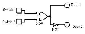
We will start with a simple problem one that is very common for most technic Users. We have 2 or more Metal doors to an Entrance. We know that one door will open and the other will close if they are side by side it is a very annoying thing to have to have only one door, or worse have lots of switches or buttons to open/close each door manually. However this problem can be easily fixed using Logic gates and some preparation.
Lets break down this problem. First we only want 2 switches one for outside and one for inside. Second we only want to open these two Doors at once. So we have only one output. Lets also say that we want theses doors Closed only when both the switches are in the same place.
Switch Switch Outside Inside | Door
 OFF      OFF    | CLOSED
 OFF      ON     | OPEN
 ON       OFF    | OPEN
 ON       ON     | CLOSED
As we can see in the table above This is the desired operation of our circuit. If you have ever taken a logic course this should look familiar to you, this table represents the logic of exclusive or, we happen to have a Gate that works in the same way, a XOR gate. Here is our Logic Circuit from logisim
Truth Tables
These Tables represent your input and output, and the combinations you can have. You will have 2^n combinations of input where n is the number of inputs. For example we have 2 inputs so our total combinations result in 4 Like the table in the simple example. For General Purposes you'll rarely need to go over 4 inputs, and well if you do you'll need machine help to reduce. 4 Inputs is the recommended max for simple logic circuits to be simplified by hand (4 inputs will result in 16 combinations). Count UP in binary from the top of the table to the bottom.
The Binary 0 = OFF The Binary 1 = ON Represent Each Input With a single letter. Output is on when your desired input combination is active
Example: Input|output a b c | e 0 0 0| 0 |m0 0 0 1| 0 |m1 0 1 0| 0 |m2 0 1 1| 0 |m3 1 0 0| 0 |m4 1 0 1| 1 |m5 1 1 0| 1 |m6 1 1 1| 1 |m7 BINARY DECIMAL
Boolean Algebra Logic Gates
There is A LOT to cover with Boolean Algebra so i'll just give you what i think you will need to know, if you want more look it up on the net. The Basic Rules Multiplication = AND logically Addition = OR logically ~ = NOT logically (if P was =0 then ~P = 1) There are 17 Identities to Boolean algebra used to reduce the equations, they are nice however we don't need to know them if we can use K-maps.
Translating your Table Into a Boolean Algebraic Expression. In the truth table section the example table has a list of base10 numbers with lower case m's beside them like m0. These's are called the Sum of min terms we use these in K-map reduction. But they also represent The variables we want to see in an Algebraic Expression. Its quite simple the number in binary is the min term's number, and the binary number itself represents the Algebraic expression. when converting from Binary to algebraic 0 = ~variable and 1 = variable.
For example: 000 is = 0 in base10 so its min term is 0 and it's algebraic representation is ~a*~b*~c.
The min terms we use are the ones that the output = 1 on. In the table example there the min terms are m5,m6,m7 and can be represented buy the algebraic expression:
m5 m6 m7 min terms
1 0 1, 1 1 0, 1 1 1 Binary a*~b*c + a*b*~c + a*b*c Algebraic
Translating Your Boolean Algebraic equation into logic gates X*Y = AND gate X+Y = OR gate ~X = NOT gate ~(X*Y) = NAND gate ~(X+Y) = NOR gate (X*Y)+(~X*~Y) = XOR gate (~X*Y)+(X*~Y) = NOR gate
So if we have the expression a*b+a*~b then we would need 2 AND gates, 1 NOT gate, and 1 OR gate, and it would look like this:
as a general Rule start with multiplication (AND gates) first.
I have been using painterly tutxere pack for a long time, and always with lighter shaded default stone. I found dark grey fatally depressing, since I like to build houses in mountains' sides and make them look like carved out of native stone.Introduction of Marble will let me switch back to grey default stone and actually WORK towards making my dwelling nice and bright.
Advanced
Flip-flops and Latches
These Circuits can store information in different states. The only latch that Red power gives you is the RS latch, the simplest latch. IMO it would have been better to give us the JK flip-flop because it can be easily made into other Latches and flip flops. Understand that the reason behind this is because they are using only circuits that operate with 4 sides and most Flip Flops need at least 5 inputs, so RS is about as good as it will get. They also could have given us the d-flipFlop as they also only need 4 sides, and would have been much more useful than the RS flip-flop, but didn't for some reason...
Check this out for Circuit diagrams and information regarding the circuits. http://en.wikipedia.org/wiki/Flip-flop_(electronics)#JK_flip-flop
I will be using D flip-flops because for State tables D Flip-Flops are very easy to use. However if your going to build a d-flipflop don't use a RS latch instead build one out of 4 NAND gates and 1 inverter, you will get fewer errors this way.
Here is The D-FlipFlop using a RS Flip-Flop DON'T BUILD IT THIS WAY!
(in logisim you will need to also use the clock input to check operation or just use D-flipflops)
MAKE YOUR D-FLIP FLOPS THIS WAY! Here is the better version of a D flip-flop Using NANDS
For the most part we attach the clock signal to the E (enable) input, and the Data we want to store in the D (data) input. No matter what the d input is the output will only change on a clock pulse or while enable is on.
Multiplexers
These are like digital switches, they also can be used as NOT gates, AND gates, and OR gates. Multiplexers are also similar to Decoders, Encoders and Demultiplexers. Those will be covered later.
Multiplexer and it acting as a logic gate. A 2-1 Mux is as simple as it gets.
The multiplexer has 2^n inputs and n controls. When the control is on it selects the input Labeled Input 1 to output, when the control is off it selects the input labeled Input 0. So if the selector was 0, and Input_0 was 1 then the output would be 1.
Here is an example of a 8-1 Mux.
Here is a table on how it works
S3 S2 S1 | Input Selected to Output
0   0   0  |  0
0   0   1  |  1
0   1   0  |  2
0   1   1  |  3
1   0   0  |  4
1   0   1  |  5
1   1   0  |  6
1   1   1  |  7
Binary | Decimal (base 10)
Encoders and Decoders
These are not very hard at all. They are used mostly to compress information, or expand information. An encoder can take lots of inputs and turn them into a few outputs, while a decoder takes a few inputs and makes more. the smallest you can make one is a 1 to 2 decoder , and an encoder 2 to 1. This is very useful if you want to transmit information without it taking up a lot of wires.
Some Rules about decoders and encoders: 1) The number of inputs for an encoder is 2^N 2) The number of outputs for an is N 3) The Opposite is true for Decoders.
An example of an encoder; If you had 4 inputs then you would have 2 outputs because n=2 if 2^n =4. Here is the truth table for an encoder 3 2 1 0 | B1 B2 0 0 0 1 | 0 0 0 0 1 0 | 0 1 0 1 0 0 | 1 0 1 0 0 0 | 1 1 Here's an encoder. One problem with this type it that it must always have some input, or you will be getting a default output which you might not desire.
This is a priority encoder, which lets you know if there is any actual input into the encoder, via the bottom output.
Decoders
These are just the opposite of encoders. Here is the truth table for a 2-4 decoder.
B C | m0 m1 m2 m3
0   0  |  1    0   0    0
0   1  |  0    1   0    0
1   0  |  0    0   1    0
1   1  |  0    0   0    1
The output is the min term of the binary input.
Here is a 2-4 decoder with enable (E)
I added an enable because you'll be outputting m0 constantly if i didn't. It also works well with the priority encoder.
Here is a Priority encoder to a decoder with enable.
Other Circuits
Here I will cover Adders, Registers, even and odd parity, Grey code and how to build every circuit out of only NAND gates.


